
Trimming paths
This tutorial will give you some insights on how to adjust paths’ trimming parameters in order to get optimal results. As an example case study we are using a 10 ns MD simulation of murine soluble epoxide hydrolase structure (PDB ID: 1CQZ).
Lengths of paths
The general rule is that paths are limited to the scope area. The bigger scope is the longer are the paths, see Figure 1. AQUA‑DUCT supports definition two types of the scope definition: direct or convex hull. In both cases user can decide on the size of the scope. For example, broad direct scope definition could be: not protein around 3 protein. This will select all non‑protein residues within 3 Å from the protein. By changing distance value in this definition one can decide on the size of the scope. Another possibility is to change the definition to select residues within different molecular entity: not protein around 3 backbone. Similarly, in case of convex hull type of definition of the scope, its extent can also be adjusted to. For example, to set scope to convex hull of protein, protein but hydrogen atoms, protein backbone, and Cα atoms, following scope definitions have to be used: protein, not name H and protein, backbone, name CA.
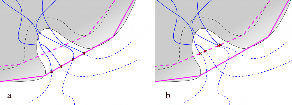
Fig. 1. Lengths of paths depends on the scope definition. Protein represented as gray shape, backbone as dashed gray line. Paths represented as blue lines, dashed if trimmed. Points of trimming indicated with red x signs: a) scope defined as protein – purple line schematically shows the convex hull shell of protein atoms; b) scope defined as backbone – dashed purple line shows the convex hull shell of backbone atoms.
Changing the definition of the scope is not the only way to influence lengths of paths. Additional trimming of paths can be done with Auto Barber procedure at III stage of AQUA‑DUCT calculations. Auto Barber works by creating a set of spheres and removing parts of paths that are inside of any spheres. Centers of spheres used by Auto Barber are set to the ends of paths that are at the edge of the scope. Radii are set to distance from the centers to the nearest atom of user defined molecular entity, see Figure 2. There are number of options allowing for adjustment of radii, positions of centers depends on the scope definition.
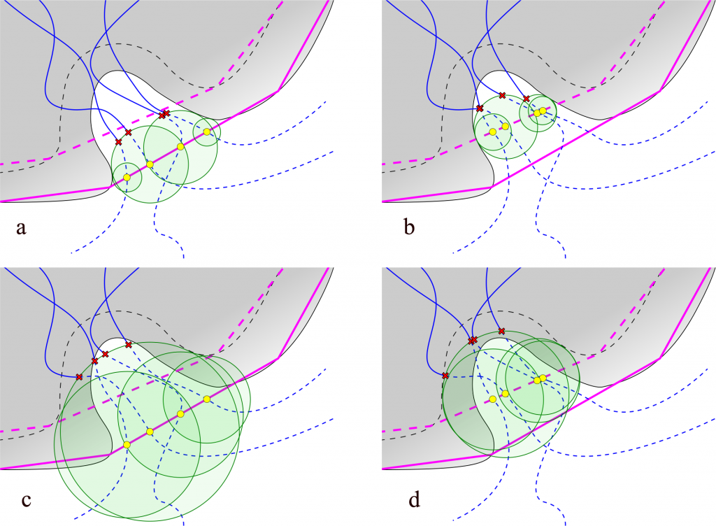
Fig. 2. Lengths of paths depends on Auto Barber settings. Auto Barber spheres are represented as green discs. Yellow spots represents points on the scope edge: a) scope set to protein, auto_barber set to protein; b) scope set to backbone, auto_barber set to protein; c) scope set to protein, auto_barber set to backbone; d) scope set to backbone, auto_barber set to backbone.
……..
Please download full tutorial here: TIPS_AND_TRICKS_TRIMMING_PATHS